One of the most fundamental architectural decisions in network design is how much traffic to keep at Layer 2 (Data Link) and when to move it up to Layer 3 (Network). For beginners, or anyone studying infrastructure architecture, one question comes up again and again: if the devices sit in the same building, or even on the same switch, why not just leave everything on a single flat Layer 2 network? Why bother creating VLANs and adding Layer 3 switching and routing layers in between?
In this article, we take an engineering look at the hardware and logical limits of a flat Layer 2 network, how Layer 3 switching (L3 Switching) works, and the transformation a packet goes through as it crosses between the two layers.
1. The Limits of Staying on a Single Layer 2 Network: Broadcast and Hardware Load#
When every device on a network sits in the same Layer 2 domain (Broadcast Domain), every broadcast packet sent by a device — ARP requests or DHCP discovery packets, for example — reaches every other device on the network.
As a Layer 2 network grows without proper scaling, two fundamental problems emerge:
- Broadcast Storms and CPU Load: As the number of devices on the network grows, the volume of broadcast packets grows exponentially with it. Since network interface cards have to process these packets, CPU load rises on both end-user devices and switches.
- MAC Address Table (CAM Table) Bloat: L2 switches forward packets based on their MAC address tables. As the network grows, these tables get pushed to their capacity limits, and hardware lookup times get longer.
The way to overcome these limits is to divide the network into logical segments — VLANs. But once VLANs are created, a new question arises: how will these different segments communicate with each other?
2. The Logic of Layer 2 vs. Layer 3 Switching#
Layer 2 switching operates entirely on MAC addresses and Ethernet frames. When devices are on the same subnet, the source device learns the destination device’s MAC address via ARP, and the switch can carry out this forwarding in hardware — using ASIC chips — at line rate.
Layer 3 switching, on the other hand, operates on IP addresses and packets. When devices on different VLANs or subnets need to communicate, Layer 2 switching alone falls short. This is where the Switched Virtual Interface (SVI) and IP routing mechanisms come into play.
3. Where the Line Falls Between a Classic Router and an L3 Switch#
If you already have a Router, why use a Layer 3 Switch (L3 Switch)? Or, conversely, if you have an L3 Switch, why would you need a Router?
Even though both devices are capable of IP routing, their architecture and hardware design serve different purposes:
- L3 Switch (Inter-VLAN Routing): Makes the routing decision directly through hardware — ASIC or CEF (Cisco Express Forwarding) tables — rather than through a software-based CPU. This lets it route inter-VLAN traffic on the local network at gigabit/terabit wire-speed with extremely low latency.
- Router (Edge / WAN Boundary): Generally designed to run more complex routing protocols (BGP, etc.), wide area network (WAN) technologies, NAT (Network Address Translation), in-depth security, and VPN tunneling processes. Its port density is lower than an L3 Switch’s, but its packet-processing capabilities are more flexible.
In short: an L3 Switch handles high-speed routing between VLANs within a building or data center, while a Router manages the boundary out to the wider world or to other locations.
4. Network Segmentation: Balancing Security and Performance#
The biggest advantage Layer 3 switching brings is network segmentation. Breaking the network into smaller broadcast domains doesn’t just improve performance — it also draws clear security boundaries.
By defining Access Control Lists (ACLs) on the L3 Switches or firewall layers placed between different VLANs, rules such as “the HR VLAN may only reach specific services on the Server VLAN, while IoT devices cannot reach any internal network at all” become logically enforceable.
5. Packet Flow Analysis: What Happens When a Packet Changes Layers?#
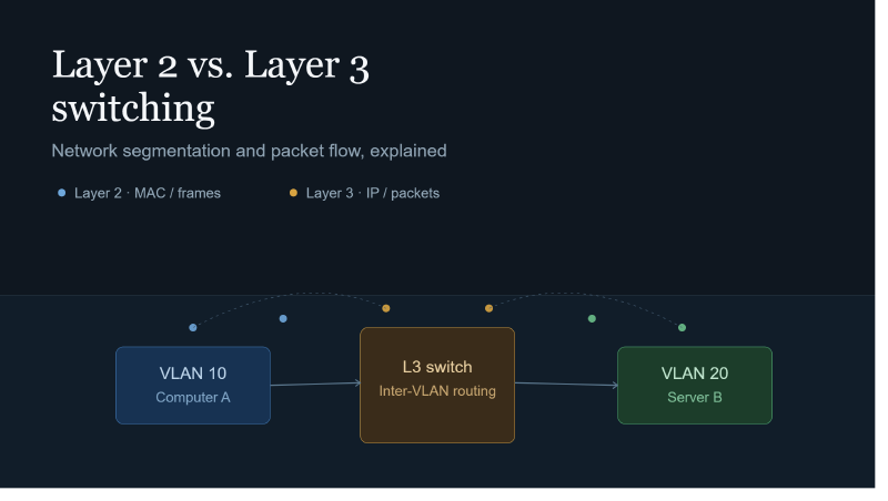
To fully understand the architecture, it helps to trace a packet’s path step by step. For example, here’s what happens when Computer A on VLAN 10 wants to send a data packet to Server B on VLAN 20:
- Subnet Check: Computer A compares its own IP address and subnet mask against Server B’s destination IP address, and determines that it’s on a different network.
- Forwarding to the Default Gateway: The packet is sent not directly to Server B’s MAC address, but to the MAC address of Computer A’s own Default Gateway (the SVI interface on the L3 Switch).
- L2 Header Rewrite: When the L3 Switch receives the packet, it NEVER changes the Source and Destination IP addresses in the IP header (Layer 3) — it only decrements the TTL value by 1. However, as the packet leaves the L3 Switch and heads toward Server B on VLAN 20, the Ethernet header (Layer 2 frame header) is rewritten: the source MAC address becomes the L3 Switch’s VLAN 20 interface, and the destination MAC address becomes Server B’s MAC address.
- Delivery: The packet is delivered to Server B at Layer 2, within VLAN 20.
Conclusion#
Layer 2 and Layer 3 technologies shouldn’t be seen as competitors, but as complementary parts of a single architecture. Switching keeps traffic local and at hardware speed, while Routing turns those local domains into controllable, secure, and scalable structures. In a well-designed network architecture, Layer 2 boundaries are kept as narrow as possible, and traffic is pulled up to Layer 3 — and managed there — as quickly as it can be.