Introduction#
Building redundancy into a Layer 2 (Data Link) network requires physically wiring up more than one cable or switch connection. But unlike an IP header, the Ethernet header has no TTL (Time to Live) field. As a result, when a loop forms in a redundant Layer 2 network, broadcast packets can circulate forever, MAC address tables get corrupted, and the entire network can lock up — a Broadcast Storm.
STP (IEEE 802.1D), and its faster successor RSTP (IEEE 802.1w), detect physical loops in the network and logically place certain ports into a blocking state.
1. The Root Bridge Election Mechanism#
At the center of every STP topology sits a Root Bridge. Every switch on the network sends BPDU (Bridge Protocol Data Unit) packets to its neighbors, and through this exchange, the network elects a Root Bridge.
The election criterion is the switch with the lowest Bridge ID (BID). Contrary to the common simplified explanation, the BID isn’t made up of just two components — it has three:
Bridge ID = Priority + Extended System ID (VLAN ID) + MAC Address- Priority: Defaults to 32768, and can be manually adjusted in increments of 4096.
- Extended System ID: Because PVST+ environments run a separate STP instance per VLAN, this field identifies which VLAN a given BPDU belongs to, and it’s folded into the Priority value.
- MAC Address: If priority values are tied, the switch with the lowest MAC address wins.
In a well-designed network, Root Bridge election is never left to chance: the priority of the core (backbone) switches is manually lowered — to, say, 4096 or 8192 — with a secondary Root Bridge candidate assigned the next tier up (e.g. 8192 or 16384).
2. Port Roles, States, and Path Cost#
Once the Root Bridge is elected, every switch port on the network is assigned a specific role:
- Root Port (RP): On every switch other than the Root Bridge, this is the port that reaches the Root Bridge over the shortest / cheapest path (exactly one per switch).
- Designated Port (DP): The port responsible for forwarding traffic on a given network segment. Every active port on the Root Bridge is a DP by default.
- Alternate / Backup Port (AP/BP): Redundant ports kept in a blocking/discarding state precisely to prevent a loop.
“Cheapest path” isn’t a vague phrase — STP calculates it numerically through Path Cost values. Here is the updated (short) IEEE 802.1D cost table:
| Link Speed | Path Cost (STP short value) |
|---|---|
| 10 Mbps | 100 |
| 100 Mbps | 19 |
| 1 Gbps | 4 |
| 10 Gbps | 2 |
A switch calculates the total cost of every possible path to the Root Bridge — the sum of the cost values of every port along that path — and elects the port with the lowest total cost as its Root Port.
3. 802.1D STP vs. 802.1w RSTP Port States#
In classic STP, getting a port into an active (Forwarding) state can take 30 to 50 seconds. RSTP cuts this down to milliseconds through a Proposal/Agreement handshake mechanism.
| 802.1D STP State | 802.1w RSTP State | MAC Learning | Traffic Forwarding |
|---|---|---|---|
| Disabled | Discarding | No | No |
| Blocking | Discarding | No | No |
| Listening | Discarding | No | No |
| Learning | Learning | Yes | No |
| Forwarding | Forwarding | Yes | Yes |
RSTP also adds two new concepts to port roles: the Edge Port (equivalent to PortFast — a port connected directly to an end-user device) and pre-computed Alternate/Backup ports — when a link goes down, RSTP doesn’t search for an alternate path from scratch the way STP does; it immediately activates an already pre-determined backup port.
4. STP Timers: Where the 30-50 Seconds Actually Comes From#
Classic STP’s slowness isn’t arbitrary — it’s the sum of three timers:
- Hello Timer (2 sec): The Root Bridge broadcasts a BPDU every 2 seconds.
- Max Age (20 sec): If a switch doesn’t receive a BPDU from its neighbor for 20 seconds, it assumes the topology has changed.
- Forward Delay (15 sec × 2): A port spends 15 seconds each in the Listening and Learning states.
In total: Max Age (20 sec) + 2 × Forward Delay (2 × 15 sec) = 50 seconds is the worst-case convergence time. In better-case scenarios, such as a direct neighbor loss, this drops to roughly 30 seconds.
RSTP abandons this waiting logic entirely: neighboring switches perform a Proposal/Agreement handshake, and as soon as each switch confirms its neighbor is in sync, the port moves straight into the Forwarding state. The result is sub-second convergence in most topologies.
5. A Convergence Scenario: What Happens When a Link Goes Down?#
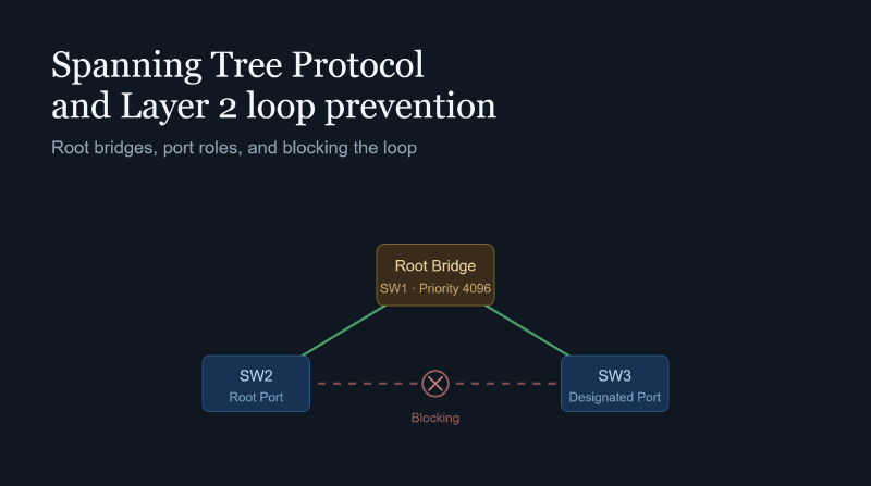
Take a triangle topology of three switches (SW1 = Root Bridge, with SW2 and SW3 each connected to each other and to the Root). The SW2-SW3 link was in an Alternate/Blocking state.
- Link-Down Detection: If the physical link between SW1 and SW2 fails, SW2 detects this immediately through the physical link-down signal.
- Topology Change Notification (TCN): SW2 sends a Topology Change BPDU directly toward the Root Bridge in RSTP (or the classic TCN BPDU chain in STP).
- MAC Table Flush: Every switch that receives the topology change notification invalidates the old paths in its MAC address table — after the Forward Delay in STP, instantly in RSTP.
- Recalculation: SW2 realizes it can now reach the Root Bridge through SW3; the SW2-SW3 Alternate Port gets promoted to Root Port.
- New Path Activation: In RSTP, because this port was already “pre-computed” and ready, it moves into Forwarding within milliseconds. In classic STP, this port has to cycle through Blocking → Listening → Learning → Forwarding all over again — and this is exactly where the 30-50 second delay is incurred.
6. PVST+, Rapid PVST+, and MST#
Everything described above assumes a single STP instance, but real-world Cisco environments run in one of three distinct modes:
- PVST+ (Per-VLAN Spanning Tree Plus): Runs a separate, independent STP instance per VLAN. This allows a different Root Bridge to be elected per VLAN, and therefore lets traffic be load-balanced across different links — for example, VLAN 10 might use SW1 as its Root Bridge while VLAN 20 uses SW2.
- Rapid PVST+ (RPVST+): PVST+ running with RSTP’s fast-convergence logic — the mode Cisco recommends as the default today.
- MST (Multiple Spanning Tree — IEEE 802.1s): In large environments with hundreds of VLANs, running a separate instance per VLAN is CPU-expensive. MST reduces that overhead by grouping multiple VLANs into a single STP “instance” (a region).
7. Layer 2 Network Security and Port Protection Mechanisms#
STP doesn’t just prevent loops — misconfigured, it can also open a security hole. A malicious device could send BPDUs with a lower Priority and declare itself the Root Bridge. The following protection mechanisms exist to prevent exactly that:
- PortFast: On ports connected to end-user devices like servers or PCs, this skips the Listening/Learning stages and lets the port jump straight into the Forwarding state.
- BPDU Guard: If a BPDU packet arrives on a port configured with PortFast (for example, if a user plugs in an unauthorized switch), the port is immediately placed into err-disable mode to protect the network.
- Root Guard: Prevents an unauthorized switch from becoming the network’s Root Bridge. If a superior BPDU arrives on a protected port, that port is placed into a root-inconsistent state and traffic is cut off.
- Loop Guard: Prevents an Alternate port from mistakenly transitioning into Forwarding — and creating a loop — during a physical link fault such as a unidirectional link failure.
Two historical Cisco features that predate RSTP also belong to this family, developed specifically to shorten classic STP’s 30-50 second convergence time: UplinkFast (lets a switch move to a backup uplink without waiting through Forward Delay when it loses its direct neighbor link) and BackboneFast (detects an indirect link failure without waiting out Max Age). With RSTP’s widespread adoption, both features have become largely unnecessary, since RSTP provides the same rapid convergence as a standard behavior.
8. Relationship with EtherChannel#
Two switches physically connected by more than one cable carry a loop risk from STP’s perspective, and one of those links gets forced into a Blocking state. EtherChannel (Port Channel) bundles those physical links into a single logical interface. STP sees a port-channel as a single port — so no loop forms, and every bundled physical link stays active simultaneously (load-balanced). This is the standard way to increase bandwidth without disabling STP.
9. A Basic CLI Configuration Example#
On Cisco IOS, the mechanisms described above translate roughly into the following commands:
! Manually lower the Root Bridge priority (on a core switch)
Switch(config)# spanning-tree vlan 10 priority 4096

! Enable Rapid PVST+ mode
Switch(config)# spanning-tree mode rapid-pvst

! PortFast + BPDU Guard on an end-user port
Switch(config)# interface fastEthernet 0/1
Switch(config-if)# spanning-tree portfast
Switch(config-if)# spanning-tree bpduguard enable

! Enable Root Guard on an uplink port
Switch(config)# interface gigabitEthernet 0/1
Switch(config-if)# spanning-tree guard root

! Enable Loop Guard globally
Switch(config)# spanning-tree loopguard default
10. What’s Replacing STP in the Modern Data Center?#
In traditional three-tier (access-distribution-core) campus networks, STP is still the standard. But in modern spine-leaf data center architectures, STP creates a problem by its very nature: because it’s fundamentally an active-passive design, it keeps a portion of redundant links permanently in a Blocking state — meaning a significant chunk of available bandwidth simply goes unused.
For this reason, large-scale data centers have shifted toward architectures that largely disable or contain STP:
- vPC (Virtual Port Channel) / MC-LAG: Makes two physical switches appear as a single logical switch, preventing STP from blocking the links between them; every link stays active-active.
- VXLAN / EVPN: Layer 2 segments get “tunneled” over a Layer 3 IP fabric, independent of the physical topology. This lets the spine-leaf fabric itself run as pure Layer 3 (with every link active via ECMP), eliminating the need for STP inside the fabric entirely — STP survives only at the outermost edge, as a safety net on the segments where end-user connections live.
Conclusion#
STP is one of the most fundamental — and most critical — security and stability layers in Layer 2 networks. From Root Bridge election to Path Cost calculation, from timers to port-protection mechanisms, every component serves a single purpose: making sure no broadcast packet ever circulates forever. RSTP and MST preserve this core logic while improving speed and scalability; modern data center architectures, rather than eliminating STP outright, choose to confine it to where it’s genuinely needed — at the edge — while moving the core to a purely Layer 3, active-active design.